
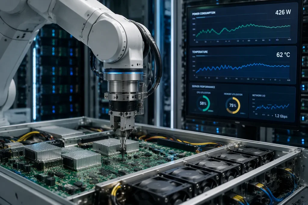
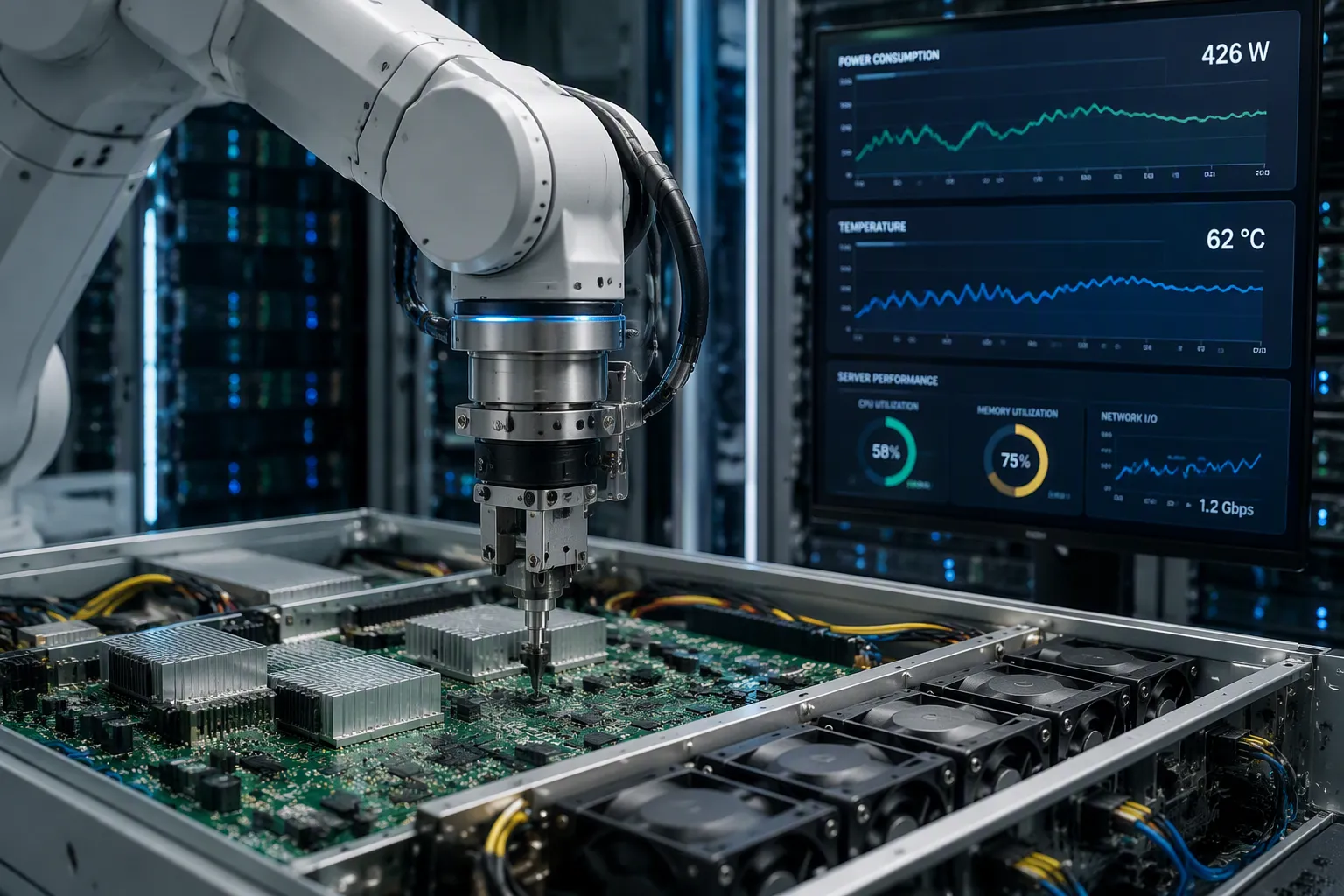
AI workloads reshape server monitoring and liquid cooling controller PCBs at a fundamental level. An AI data center PCBA must now handle extreme power densities, stringent thermal limits, and high-speed signal integrity. Two consequences follow. Server monitoring boards evolve toward higher layer counts, embedded sensors, and robust ageing verification. Liquid cooling controllers demand precise high-speed control, redundant safety monitoring, and dependable leak detection. Rising rack power density makes temperature, current, and fan management far more complex, and operators expect long-term reliability from every board. This article breaks down each area with practical, technical guidance for engineers.
Key Takeaways
AI data centres need PCBA designs that handle high power and heat.
Server monitoring boards now use embedded sensors for real-time control.
Liquid cooling controllers require precise pump control and safety monitoring.
Engineers must select advanced materials for high-speed signals.
Testing standards like AEC-Q007-2024 ensure long-term reliability.
Power Delivery for AI Data Center PCBA
Multilayer Boards and Advanced Materials for High Current
AI racks now draw far more current than traditional server racks. Designers therefore move to 48V backplane architectures. Higher voltage lowers current for the same power, which reduces resistive losses in the distribution path. This shift forces higher layer counts. A typical board may need separate layers for power, ground, and high-speed signals. Low-loss laminates preserve signal integrity at elevated data rates. They also tolerate the thermal load that dense power delivery creates. Material selection therefore becomes a power decision, not only a signal decision.
Heavy Copper, Thermal Vias, and Solder Reliability
Heavy copper layers carry the increased current without excessive heating. Thermal via arrays move heat away from hot components into internal planes. Solder joints then face constant thermal cycling. Each heating and cooling cycle stresses the joint through differential expansion. Assembly process adjustments matter here. Reflow profiles must suit the thicker copper, which absorbs heat more slowly. Preheating and soak times require careful control.
Bonysn addresses these demands through thick copper PCB fabrication and high-current soldering processes. The table below compares general capability bands.
Parameter | Conventional PCB | Bonysn thick copper PCB |
|---|---|---|
Copper weight | Standard foil | Heavy copper, suitable for high current |
Thermal management | Limited via arrays | Dense thermal via arrays |
Solder reliability | Standard reflow | Tuned reflow for heavy copper |
Engineers should verify finished assemblies against IPC-A-610 and IPC-6012 acceptance criteria. These standards define workmanship and performance expectations for rigid boards.
AI Data Center PCBA for Server Monitoring
Embedded Sensing for Thermal and Current Control
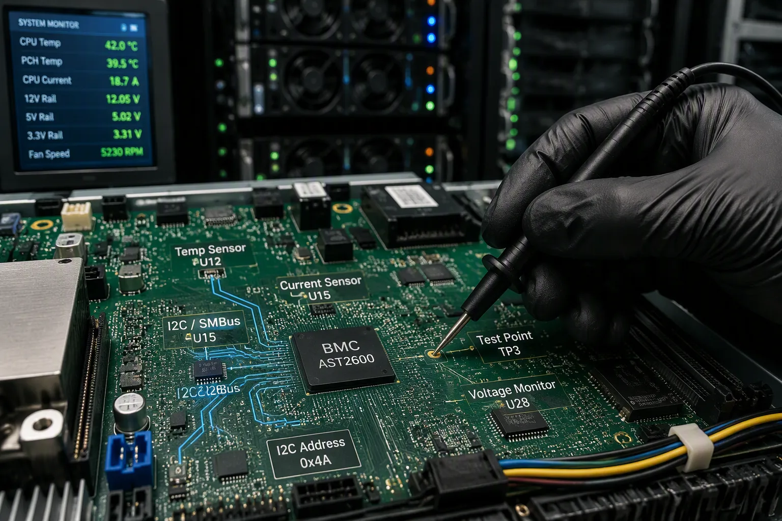
Modern server monitoring boards no longer act as passive carriers. They function as intelligent sub-systems. Designers embed temperature and current sensors directly into the PCB structure. These sensors provide real-time feedback to the baseboard management controller. The controller then adjusts fan speeds, throttles power, or triggers protective shutdowns. This closed-loop approach improves thermal management significantly. It also enables precise power capping across dense compute nodes.
Sensor data must travel from many monitoring points to a central controller. The Linux IPMI driver documentation confirms that direct I2C access to the IPMI management controller is supported on some boards through the IPMI SMBus handler. The SMBus driver can manage up to four SMBus devices using normal I2C addresses and adapter names from /sys/class/i2c-adapter/. This confirms that I2C and SMBus serve as the primary interfaces for aggregating sensor data. SPI does not appear in this context. Engineers should therefore design their AI data center PCBA with robust I2C bus routing and proper address management.
Bonysn supports these designs through plugin assembly and functional testing services. The table below compares general assembly approaches.
Capability | Conventional Assembly | Bonysn Plugin Assembly |
|---|---|---|
Sensor integration | Manual placement | Automated plugin assembly |
Functional testing | Basic continuity | Full functional verification |
Traceability | Limited records | Complete test data logging |
Signal Integrity and Ageing Verification
High-noise environments threaten signal integrity on monitoring boards. Material selection directly affects performance at elevated data rates. Standard FR4 (Dk approximately 4.3 to 4.7, Df approximately 0.02) suits speeds only up to 5 Gbps. Modified low-loss FR4 (Dk approximately 3.7, Df approximately 0.005 to 0.009) becomes the mainstream choice for AI servers and switch boards operating at 25 Gbps and beyond. Very-low-loss laminates (Df at or below 0.0025) enable 112G PAM4 channels. Ultra-low-loss materials (Df at or below 0.0020) prove essential for long-reach 112G and 224G SerDes. Designers should select materials with stable Dk (change of no more than plus or minus 0.05 to 0.1 from 1 to 10+ GHz) to maintain consistent impedance.
Accelerated ageing testing validates long-term reliability. AEC-Q007-2024 is a board-level reliability testing standard specifically applied to Auto and AI Servers. It references IPC-9701 for temperature cycling conditions, dwell times, ramp rates, and sample sizes. Key parameters include:
Temperature cycling ranges (TC1: 0°C to 100°C, TC3: -40°C to 125°C)
Dwell time of 10 to 15 minutes
Temperature change rate at or below 20°C per minute (preferably 10 to 14°C per minute)
Continuous dynamic monitoring of solder joint resistance
The standard explicitly connects to AI server monitoring PCBA reliability by stating the testing temperature range is based on the actual operating environment of the application. Engineers should apply these tests to validate their designs against real-world conditions.
Liquid Cooling Controller Integration and Design
High-Speed Pump Control and Bus Protocols
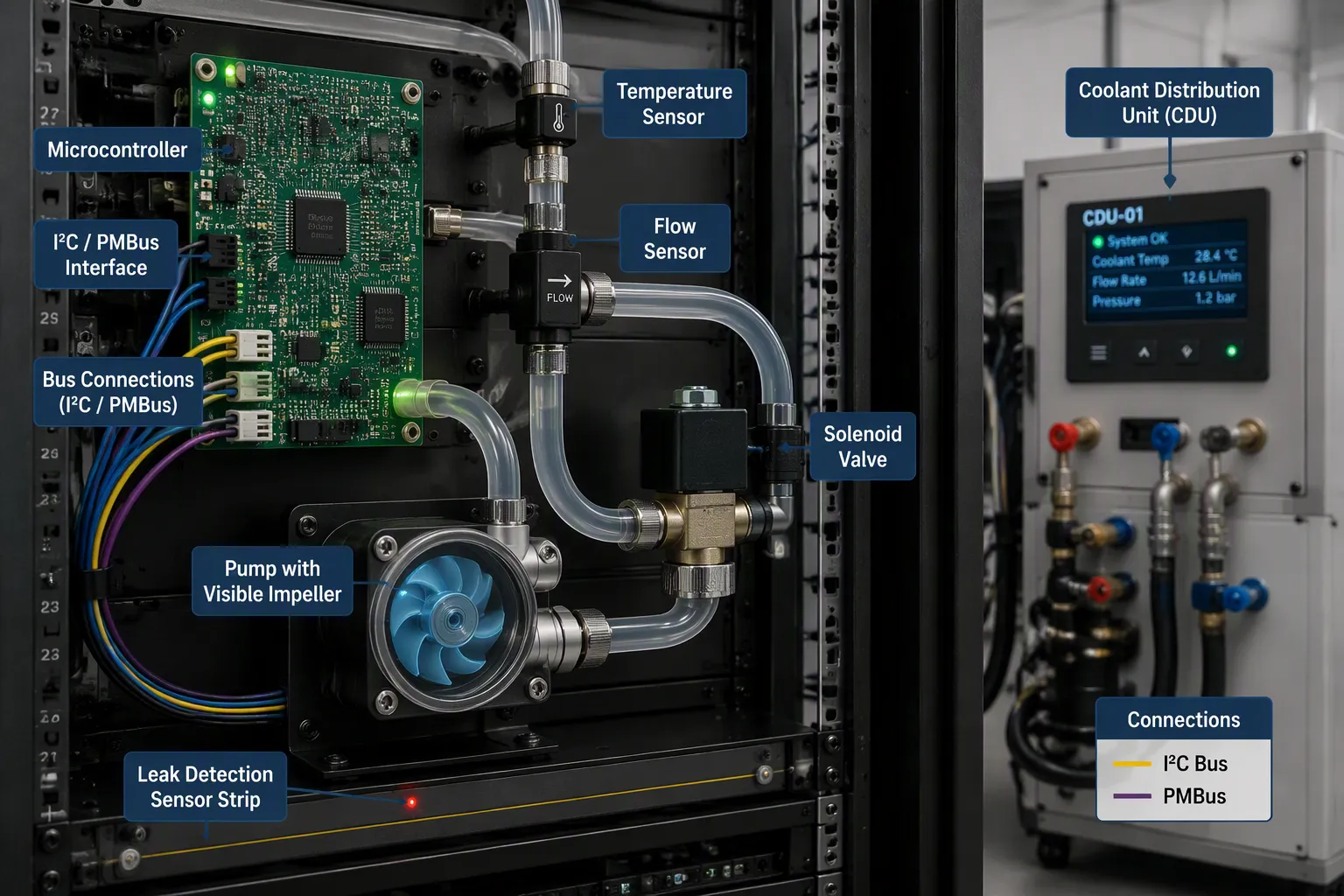
Liquid cooling controllers must modulate pump speed with precision. A pump that runs too slowly allows heat to build at the cold plate. A pump that runs too fast wastes energy and accelerates wear. The controller therefore needs a fast, deterministic command path. PMBus and I2C serve as the primary interfaces for this task. PMBus offers a standardised command set for reading telemetry and writing setpoints. I2C provides a simple two-wire bus for lower-speed devices. Both protocols allow the controller to report pump RPM, flow rate, and inlet and outlet temperatures to the baseboard management controller.
Integration with the coolant distribution unit (CDU) extends this control loop. The CDU manages facility-side flow and pressure. The controller board must exchange status and commands with the CDU over the same bus fabric. Engineers should assign unique I2C addresses to every device on the bus. Address conflicts cause silent failures that only appear under load. Bus capacitance also limits trace length and device count. Careful layout keeps the bus within its timing budget.
Safety Monitoring, Leak Detection, and Valve Circuits
Safety circuits protect the server when the cooling loop fails. Redundant monitoring paths form the first layer of defence. Two independent sensor channels measure the same critical parameter. A comparator then flags any disagreement between them. This arrangement catches a failed sensor before it hides a real fault.
Leak detection sensors sit at the lowest points of the rack and near every joint. They detect conductive fluid and trigger an immediate shutdown. Valve control logic then isolates the affected branch. The valve driver must fail safe. A loss of control power should close the valve rather than leave it open. Engineers should route valve control traces away from high-current pump traces to avoid induced noise.
The monitoring PCBA ties these functions together. It aggregates leak, flow, and temperature data, then acts on the results. This makes the AI data center PCBA a central safety node, not a passive carrier. Bonysn supports these designs through plugin assembly and full functional verification. The table below compares general assembly approaches for liquid cooling controllers.
Capability | Conventional Assembly | Bonysn Plugin Assembly |
|---|---|---|
Safety circuit testing | Basic continuity | Full functional verification |
Leak sensor integration | Manual placement | Automated plugin assembly |
Traceability | Limited records | Complete test data logging |
Engineers should validate these boards against IPC-9701 temperature cycling conditions. AEC-Q007-2024 references this standard for board-level reliability. The standard ties test temperatures to the actual operating environment. This practice confirms that safety circuits survive real thermal stress.
Three takeaways stand out. First, AI data center PCBA assembly must be re-engineered for high-power delivery and thermal resilience. Second, server monitoring boards now act as intelligent sub-systems with embedded sensing and robust verification. Third, liquid cooling controllers require tight integration with high-speed control and safety monitoring. As AI data centre densities continue to escalate, mastering these PCBA design approaches becomes a competitive advantage for system reliability and efficiency. Engineers should treat these challenges as opportunities to innovate in board layout, material selection, and assembly processes.
FAQ
What materials support high-speed signals in AI data centre PCBA?
Low-loss laminates with stable dielectric constant (change of no more than ±0.1 from 1 GHz to 10 GHz) preserve signal integrity. Modified low-loss FR4 suits 25 Gbps lines. Very-low-loss materials enable 112G PAM4 channels. Engineers select materials based on operating data rate and thermal load.
How does Bonysn validate solder joint reliability under thermal cycling?
Bonysn applies tuned reflow profiles for heavy copper layers and conducts temperature cycling per IPC-9701 (TC3: -40°C to 125°C). Continuous dynamic resistance monitoring catches early failures. This approach confirms joints survive real-world thermal stress in AI racks.
Which test standard addresses long-term reliability for server monitoring PCBA?
AEC-Q007-2024 governs board-level reliability for AI server applications. It references IPC-9701 for temperature cycling conditions, dwell times, and sample sizes. The test temperature range matches the actual operating environment, validating that monitoring boards endure sustained thermal stress.
Why does leak detection require dedicated circuits on the liquid cooling controller?
Leak sensors sit at rack low points and near joints. They detect conductive fluid and trigger immediate shutdown. Valve control logic isolates the affected branch. Failure of control power must close the valve, not leave it open, protecting downstream equipment.
Does Bonysn offer functional testing for assembled liquid cooling controller PCBA?
Yes. Bonysn performs plugin assembly followed by full functional verification of safety circuits, leak sensor inputs, and bus communication. Every board receives complete test data logging for traceability. This process catches faults before boards reach integration.
See Also
Elevated-Temperature AI Server Circuit Board Assembly for Emirates Data Centre Facilities
Artificial Intelligence Server Power Supply Board Assembly for Aussie Data and Energy Schemes
Complete AI Server Circuit Board Assembly for Singaporean Data Centre Establishments
Heavy-Current Power Distribution Printed Circuit Board for Australian AI Server Ventures
AI Inference Server Printed Circuit Board Assembly for British Edge Computing Initiatives